The structural analysis software RFEM 6 is the basis of a modular software system. The main program RFEM 6 is used to define structures, materials, and loads of planar and spatial structural systems consisting of plates, walls, shells, and members. The program also allows you to create combined structures as well as to model solid and contact elements.
RSTAB 9 is a powerful analysis and design software for 3D beam, frame, or truss structure calculations, reflecting the current state of the art and helping structural engineers meet requirements in modern civil engineering.
Do you often spend too long calculating cross-sections? Dlubal Software and the RSECTION stand-alone program facilitate your work by determining section properties of various cross-sections and performing a subsequent stress analysis.
Do you always know where the wind is blowing from? From the direction of innovation, of course! With RWIND 2, you have a program at your side that uses a digital wind tunnel for the numerical simulation of wind flows. The program simulates these flows around any building geometry and determines the wind loads on the surfaces.
Are you looking for an overview of snow load zones, wind zones, and seismic zones? Then you are in the right place. Use the Geo-Zone Tool to determine quickly and efficiently snow loads, wind speeds, and seismic data according to ASCE 7‑16 and other international standards.
Would you like to try out the capabilities of the Dlubal Software programs? You have the opportunity to do so! The free 90-day full version allows you to thoroughly test all our programs.
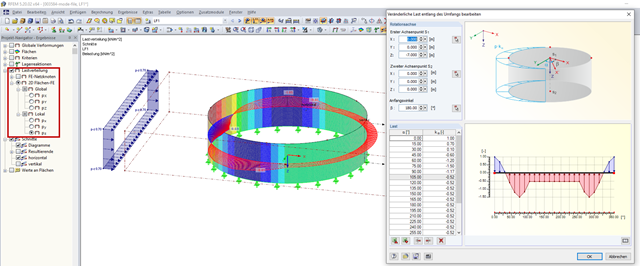
You can check the load application using Project Navigator - Results → Load Distribution. In sections, the load distribution can be displayed graphically over the perimeter and the height.
Image 01 shows the free variable load on a cylinder along the perimeter. Image 02 shows the free variable load over the height. You can clearly see the load distribution in the horizontal and vertical sections.
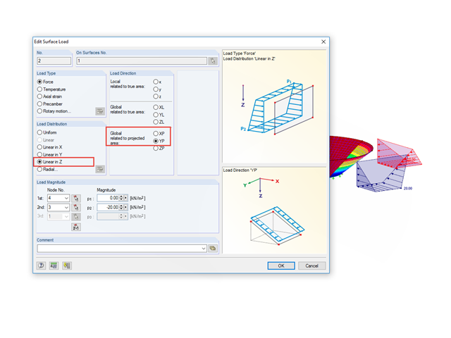
For a cylinder, the load direction could be defined locally in z, but for a hopper, the load would no longer be parallel to the XY plane.
Therefore, such a load must be divided into two components (X and Y), with the "Global related to the projected area" load direction, once XP and once YP, as well as the "Linear in Z" load distribution; see the image:
The load value may have to be converted.
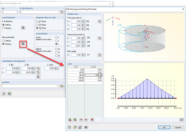
To do this, you can use the "Free Variable Load" load type. It allows you to define a load that acts variably along the perimeter, when specifying the rotation axis. Also, it is possible to separate the perimeter into several segments.
Furthermore, this load can be used to generate a load that is variable in height. In the model file provided, an example of a load with both variables is applied.
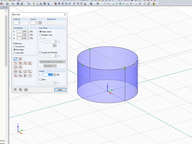
Yes, this is possible. Silos/tanks are usually made up of one curved 2D surface. This 2D surface needs to be split into two separate 2D surfaces for the cylinder to be exported into Revit. If it is only made up of one surface, then only half of the cylinder will be exported.
To do this, create a cylinder with one single surface. Then draw a line exactly adjacent to the original line that was created perpendicular to the top and bottom of the cylinder.
Next, delete the surface and recreate two surfaces using the quadrangle tool.
This process is also demonstrated in the attached video.
There is an option to convert an intersection to a line. This option allows you to create the intersection manually. Here is an example:
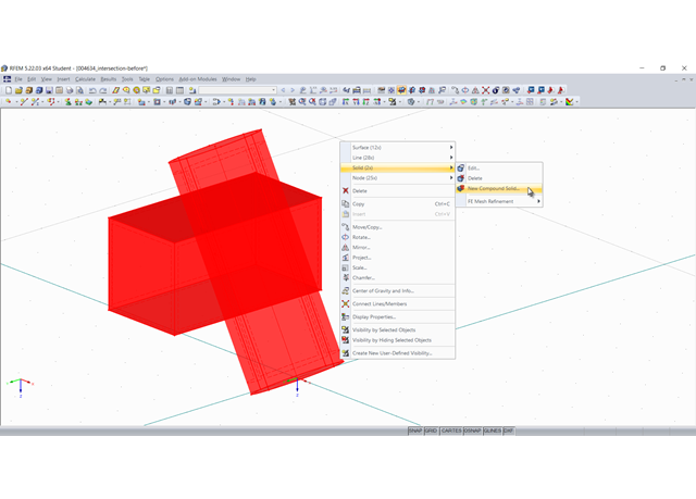
1. First, an intersection between two objects is created, here using the "New Compound Solid" command:
In this specific case, the cylinder is subtracted from the cuboid, thus creating an intersection:
2. This intersection is now "converted into lines". For this, select all involved objects and in the shortcut menu, select "Convert into Line" under "Intersection":
3. The new lines are used to create new surfaces or modify existing ones. You can change the boundary lines of a surface by selecting them again. In particular, the intersection area must be modeled as a quadrangle surface:
4. Finally, it is necessary to create the solid again: